Uploads by Matt Parnell
Jump to navigation
Jump to search
This special page shows all uploaded files.
| Date | Name | Thumbnail | Size | Description | Versions |
|---|---|---|---|---|---|
| 00:14, 29 April 2026 | FFSC-001 Pg 10 - Filter Tank Pressure Sensors.png (file) |  |
131 KB | Added Option B sensor and wiring as alternative. | 3 |
| 11:50, 28 August 2022 | FFSC-001 Pg 40 - Boiler Auxiliary.png (file) |  |
91 KB | Wiring updates for new boiler temperature controller (FFSC-006). | 3 |
| 11:26, 28 August 2022 | FFSC-001 Pg 23 - PLC Digital IO.png (file) |  |
85 KB | FFSC-001 Pg 23 - PLC Digital I/O | 1 |
| 11:24, 28 August 2022 | FFSC-001 Pg 22 - PLC Digital Outputs.png (file) |  |
102 KB | Updated Y11 and Y12, moved Y14-Y17 to a new page. | 3 |
| 11:22, 28 August 2022 | FFSC-001 Pg 21 - PLC Digital Inputs.png (file) |  |
119 KB | As-built updates; changes for pool and boiler temperature controls. | 4 |
| 13:13, 21 August 2022 | Fairway Farms Swim Club Logo.svg (file) | 106 KB | Fairway Farms Swim Club Logo | 1 | |
| 12:01, 15 January 2022 | FFSC-001 Pg 1 - Process Flow 1 of 2.png (file) |  |
115 KB | Fixed a minor drawing detail (non-functional revision). | 3 |
| 01:25, 9 January 2022 | FFSC-005 Pg 11 - Main Pump Motor VFD (GA50U2042ABA).png (file) | .png) |
116 KB | Black and white version. | 2 |
| 20:44, 6 January 2022 | FFSC-005 Pg 5 - VFD Panel Layout (GS23-2015).png (file) | .png) |
104 KB | Color version. | 2 |
| 12:23, 6 January 2022 | FFSC-005 Pg 10 - Main Pump Motor VFD (GS23-2015).png (file) | .png) |
115 KB | FFSC-005 Pg 10 - Main Pump Motor VFD (GS23-2015) | 1 |
| 01:34, 6 January 2022 | FFSC-005 Pg 10 - Main Pump Motor VFD.png (file) |  |
114 KB | FFSC-005 Pg 10 - Main Pump Motor VFD | 1 |
| 01:27, 6 January 2022 | FFSC-005 Pg 7 - VFD Panel Reactor Placement Study.png (file) |  |
116 KB | Corrected the creation date on the drawing title block. | 2 |
| 02:16, 4 January 2022 | FFSC-004 Pg 1 - Chlorinator.png (file) |  |
86 KB | Updated to FFSC-004 Pg 1 to reflect new drawing package. | 4 |
| 02:08, 4 January 2022 | FFSC-003 Pg 1 - PC2100 Wiring.png (file) |  |
77 KB | Updated to FFSC-003 Pg 1 to reflect new drawing package. | 3 |
| 01:45, 4 January 2022 | FFSC-002 Temperature Controller.png (file) |  |
115 KB | Updated the drawing title to avoid confusion (Pool Temperature Controller vs. Boiler Temperature Controller). No update to the drawing revision. | 2 |
| 15:08, 2 January 2022 | Boiler TC - Low Temp Fault.png (file) |  |
18 KB | A simulated screenshot of the Boiler Temperature Controller during a low-temperature fault. | 1 |
| 15:08, 2 January 2022 | Boiler TC - High Temp Fault.png (file) |  |
18 KB | A simulated screenshot of the Boiler Temperature Controller during a high-temperature fault. | 1 |
| 14:44, 2 January 2022 | Boiler TC - Boiler Fault.png (file) |  |
18 KB | A simulated screenshot of the Boiler Temperature Controller during a detected boiler fault. | 1 |
| 13:16, 2 January 2022 | Boiler TC - No Stage 2.png (file) |  |
18 KB | A simulated screenshot of the Boiler Temperature Controller with no Stage 2 operation. | 1 |
| 13:16, 2 January 2022 | Boiler TC - Normal Operation.png (file) |  |
18 KB | A simulated screenshot of the Boiler Temperature Controller during normal operation. | 1 |
| 12:07, 2 January 2022 | Boiler Temperature Controller Logic.png (file) |  |
41 KB | The initial revision of the Boiler Temperature Controller logic, as captured from the Graphical Wiring window in Eurotherm iTools. | 1 |
| 01:35, 22 September 2021 | Pool Systems Automation PLC.jpg (file) |  |
3.38 MB | The pool systems automation programmable logic controller and support components. | 1 |
| 01:32, 22 September 2021 | Chlorinator PLC.jpg (file) |  |
2.71 MB | The chlorinator electrical controls with custom PLC. | 1 |
| 01:03, 22 September 2021 | RBI Boiler Controls May 2021.jpg (file) |  |
3.74 MB | A photo of the RBI boiler control wiring in May of 2021. | 1 |
| 01:03, 22 September 2021 | RBI Boiler Controls May 2020.jpg (file) |  |
4.8 MB | A photo of the RBI boiler control wiring in May of 2020. | 1 |
| 14:36, 17 September 2021 | Pool Output Water Flow Meter.jpg (file) |  |
3.15 MB | The flow meter that measures the output water flow to the pool. | 1 |
| 11:36, 12 September 2021 | Pool Filter Tank Pressure Gauges.jpg (file) |  |
3.52 MB | Pool filter tank pressure gauges. | 1 |
| 11:35, 12 September 2021 | Automation Controls Near Boiler.jpg (file) |  |
3.12 MB | Various automation controls near the boiler. | 1 |
| 11:31, 12 September 2021 | Pool Controller Instrumentation.jpg (file) |  |
3.26 MB | Instrumentation for the pool controller. | 1 |
| 11:01, 12 September 2021 | Original Water Gate Valve.jpg (file) |  |
4.6 MB | The original (1965 stamped) water gate valve. | 1 |
| 21:20, 11 September 2021 | Pool Filter Tanks.jpg (file) |  |
3.67 MB | A photo of the four pool (sand) filter tanks. | 1 |
| 18:34, 9 September 2021 | Leeson C254T17DK13A Plate.jpg (file) |  |
5.74 MB | The identification plate on the Leeson C254T17DK13A pool main pump motor. | 1 |
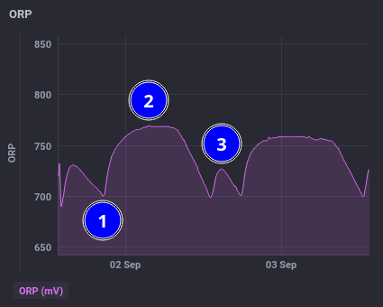
| 17:38, 3 September 2021 | ORP Graph Example.png (file) |  |
20 KB | An example of an pool systems automation ORP graph. | 1 |
| 19:31, 2 September 2021 | Inlet Temperature Gauge Example.png (file) |  |
27 KB | Updated the color band to accurately reflect the temperature controller alarm threshold. | 2 |
| 19:13, 2 September 2021 | ORP Gauge Example.png (file) |  |
27 KB | An example of a pool systems automation dashboard ORP gauge. | 1 |
| 19:12, 2 September 2021 | PH Gauge Example.png (file) |  |
24 KB | An example of a pool systems automation dashboard pH gauge. | 1 |
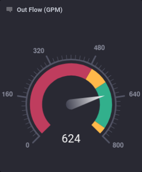
| 19:12, 2 September 2021 | Out Flow Gauge Example.png (file) |  |
28 KB | An example of a pool systems automation out flow rate gauge. | 1 |
| 18:55, 2 September 2021 | Surge Tank Depth Gauge Example.png (file) |  |
28 KB | An example of the pool systems automation dashboard surge tank depth gauge. | 1 |
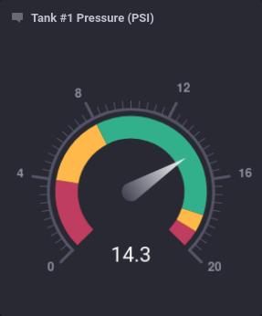
| 18:54, 2 September 2021 | Tank Pressure Gauge Example.png (file) |  |
27 KB | Included the text heading in the screenshot. | 2 |
| 23:27, 10 August 2021 | FFSC Electrical Service Wiring.png (file) |  |
73 KB | FFSC Electrical Service Wiring | 1 |
| 19:03, 1 June 2021 | FFSC-001 Pg 2 - Process Flow 2 of 2.png (file) |  |
95 KB | Corrected chlorinator output for check valve not strainer. | 2 |
| 18:17, 11 March 2021 | FFSC PA Chime MicPre.png (file) |  |
422 KB | FFSC PA Chime MicPre (preliminary drawing) | 1 |
| 14:50, 7 March 2021 | Gate Valve Overhead (6-Mar-2021).jpg (file) | .jpg) |
3.8 MB | An overhead view of the gate valve well, taken on March 6th, 2021. | 1 |
| 20:45, 23 January 2021 | FFSC-001 Pg 20 - PLC Base.png (file) |  |
116 KB | Updates to PLC serial port connections. | 3 |
| 12:39, 31 December 2020 | FFSC-001 Pg 41 - Pump House Motor.png (file) |  |
109 KB | Updated reference, wire number. | 2 |
| 19:47, 30 December 2020 | FFSC-001 Pg 12 - Water Level Sensors.png (file) |  |
90 KB | Fixed revision level. | 3 |
| 19:45, 30 December 2020 | FFSC-001 Pg 11 - Flow Meter.png (file) |  |
108 KB | Updated reference. | 2 |
| 14:32, 30 December 2020 | FFSC-001 Pg 24 - PLC Slot 2 - 0-5 V Analog Inputs.png (file) |  |
113 KB | Corrected revision level. | 3 |
| 14:30, 30 December 2020 | FFSC-001 Pg 25 - PLC Slot 3 - 4-20 mA Analog Inputs.png (file) |  |
94 KB | Added cable type, updated terminal numbers, miscellaneous fixes. | 2 |
| 19:42, 10 December 2020 | FFSC-001 Pg 5 - PLC Panel Layout.png (file) |  |
154 KB | FFSC-001 Pg 5 - PLC Panel Layout | 1 |